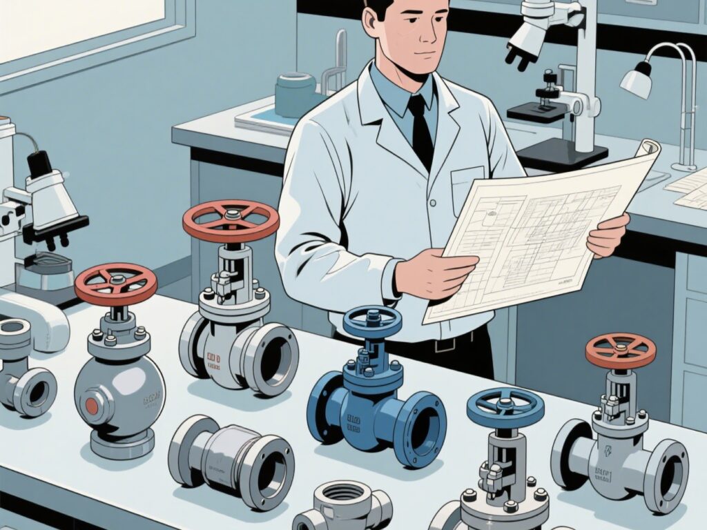
I. Valve Selection and Installation Locations
(A) Principles for Selecting Valves in Water Supply Pipes
- For pipes with a diameter not greater than 50mm, globe valves are preferred; for diameters larger than 50mm, gate valves or butterfly valves are recommended.
- When flow rate and water pressure need to be adjusted, regulating valves or globe valves should be used.
- In locations requiring low water flow resistance (such as on the suction pipe of a water pump), gate valves are suitable.
- Gate valves or butterfly valves should be used on pipe sections where water needs to flow bidirectionally; globe valves must not be used.
- Butterfly valves or ball valves are ideal for installations with limited space.
- Globe valves are recommended for pipe sections that need frequent opening and closing.
- Multi-functional valves are suitable for the outlet pipes of large-diameter water pumps.
(B) Locations Where Valves Should Be Installed on Water Supply Pipes
- On the incoming pipe section where the residential community water supply pipe connects to the municipal water supply pipe.
- At the nodes of the outdoor ring-shaped pipe network in the residential community, valves should be installed according to separation requirements. If the ring-shaped pipe section is too long, sectional valves should be installed.
- At the start of the branch pipe or household connection pipe connected from the main water supply pipe of the residential community.
- On the household pipe, water meter, and each branch riser (at the bottom of the riser, and at the upper and lower ends of the vertical ring-shaped pipe network risers).
- On the branch mains of the ring-shaped pipe network and the connecting pipes of the through branch-shaped pipe network.
- At the start of the distribution pipe connected from the indoor water supply pipe to households, public toilets, etc. A valve should be installed when there are 3 or more water distribution points on the distribution branch pipe.
- On the outlet pipe of the water pump and the suction pipe of the self-priming pump.
- On the inlet pipe, outlet pipe, and drain pipe of the water tank.
- On the water supply and make-up pipe of equipment (such as heaters, cooling towers, etc.).
- On the distribution pipes of sanitary fixtures (such as toilets, washbasins, showers, etc.).
- Before and after certain accessories, such as automatic air release valves, pressure relief valves, water hammer eliminators, pressure gauges, sprinklers, etc., and before and after pressure reducing valves and backflow preventers.
- A drain valve should be installed at the lowest point of the water supply pipe network.
(C) Check Valves
Check valves should generally be selected based on factors such as their installation location, the water pressure before the valve, the tightness requirements after closing, and the magnitude of water hammer caused during closing.
- When the water pressure before the valve is low, swing-type, ball-type, and shuttle-type check valves are preferred.
- If tightness after closing is strictly required, check valves with closing springs should be selected.
- To reduce closing water hammer, quick-closing silent check valves or slow-closing check valves with damping devices are suitable.
- The disc or valve core of the check valve should be able to close automatically under the action of gravity or spring force.
(D) Pipe Sections Where Check Valves Should Be Installed on Water Supply Pipes
- On the incoming pipe;
- On the inlet pipe of closed water heaters or water-using equipment;
- On the outlet pipe of the water pump;
- On the outlet pipe section of water tanks, water towers, and highland water pools where the inlet and outlet pipes share a single pipe.
Note: If a pipe backflow preventer is installed on the pipe section, there is no need to install a check valve.
(E) Locations Where Air Release Devices Should Be Installed on Water Supply Pipes
- For intermittently used water supply pipe networks, automatic air release valves should be installed at the end and highest point of the pipe network.
- For pipe sections of the water supply pipe network with obvious undulations where air accumulates, automatic air release valves or manual valves for air release should be installed at the peak of the section.
- For pressure water supply devices, when using an automatic air-supplementing pressure water tank, an automatic air release valve should be installed at the highest point of the distribution pipe network.
II. Advantages and Disadvantages of Various Valves
1. Gate Valve
A gate valve is a valve where the closing part (gate) moves in the direction perpendicular to the axis of the passage. It is mainly used to cut off the medium in the pipeline, i.e., for full opening or full closing. Generally, gate valves cannot be used to regulate flow. They can be applied to both low-temperature and low-pressure, and high-temperature and high-pressure conditions, depending on the different materials of the valve. However, gate valves are generally not used in pipelines transporting media such as mud.
Advantages:
- Low fluid resistance;
- Small torque required for opening and closing;
- Can be used in ring-shaped pipelines where the medium flows in both directions, meaning the flow direction of the medium is not restricted;
- When fully open, the sealing surface is less eroded by the working medium compared to globe valves;
- The structure is relatively simple, and the manufacturing process is good;
- The structural length is relatively short.
Disadvantages:
- Large overall dimensions and opening height, requiring a large installation space;
- During the opening and closing process, the sealing surfaces rub against each other, causing significant wear, and even scratching at high temperatures;
- Generally, gate valves have two sealing surfaces, which increases the difficulty of processing, grinding, and maintenance;
- Long opening and closing time.
2. Butterfly Valve
A butterfly valve is a valve that uses a disc-shaped closing part to rotate approximately 90° back and forth to open, close, and regulate the fluid passage.
Advantages:
- Simple structure, small size, light weight, and material-saving, especially suitable for large-diameter valves;
- Quick opening and closing, with low flow resistance;
- Can be used for media with suspended solid particles, and can also be used for powdery and granular media depending on the strength of the sealing surface. It is widely used in the two-way opening, closing, and regulation of ventilation and dust removal pipelines, and in gas pipelines and waterways in metallurgy, light industry, electric power, petrochemical systems.
Disadvantages:
- The flow regulation range is not large; when the opening reaches 30%, the flow will be more than 95%.
- Due to the limitations of the structure and sealing materials, it is not suitable for high-temperature and high-pressure pipeline systems. Generally, the operating temperature is below 300°C and the pressure is below PN40.
- The sealing performance is relatively poor compared to ball valves and globe valves, so it is used in places where the sealing requirements are not very high.
3. Ball Valve
Derived from plug valves, a ball valve is a valve where the closing part is a ball, and the opening and closing are achieved by rotating the ball 90° around the axis of the valve stem. Ball valves are mainly used to cut off, distribute, and change the flow direction of the medium in the pipeline. Ball valves designed with V-shaped openings also have good flow regulation functions.
Advantages:
- The lowest flow resistance (actually zero);
- Can be reliably used in corrosive media and low-boiling point liquids because it will not get stuck during operation (even without lubricant);
- Can achieve complete sealing within a wide range of pressure and temperature;
- Can realize quick opening and closing; some structures have an opening and closing time of only 0.05~0.1s, which ensures their use in the automatic system of test benches. There is no impact during operation when opening and closing the valve quickly;
- The spherical closing part can be automatically positioned at the boundary position;
- The working medium is reliably sealed on both sides;
- When fully open and fully closed, the sealing surfaces of the ball and valve seat are isolated from the medium, so the medium flowing through the valve at high speed will not cause erosion to the sealing surfaces;
- Compact structure and light weight; it can be considered the most reasonable valve structure for low-temperature medium systems;
- The valve body is symmetrical, especially the welded valve body structure, which can well withstand the stress from the pipeline;
- The closing part can withstand high pressure difference when closed;
- Fully welded body ball valves can be directly buried underground, preventing the internal parts of the valve from being corroded, with a maximum service life of 30 years, making them the most ideal valves for oil and gas pipelines.
Disadvantages:
- The most important valve seat sealing material for ball valves is polytetrafluoroethylene (PTFE), which has comprehensive characteristics such as chemical inertness to almost all chemical substances, low friction coefficient, stable performance, resistance to aging, wide temperature application range, and excellent sealing performance. However, the physical properties of PTFE, including a high expansion coefficient, sensitivity to cold flow, and poor thermal conductivity, require that the design of the valve seat seal must be based on these characteristics. Therefore, when the sealing material hardens, the reliability of the seal is compromised. Moreover, the temperature resistance level of PTFE is relatively low, and it can only be used at temperatures below 180°C. Beyond this temperature, the sealing material will age. For long-term use, it is generally only used at temperatures below 120°C.
- Its regulating performance is worse than that of globe valves, especially for pneumatic valves (or electric valves).
4. Globe Valve
A globe valve is a valve where the closing part (valve disc) moves along the centerline of the valve seat. According to this movement form of the valve disc, the change in the valve seat opening is proportional to the stroke of the valve disc. Due to the relatively short opening or closing stroke of the valve stem of this type of valve, and its very reliable cutting function, and because the change in the valve seat opening is proportional to the stroke of the valve disc, it is very suitable for flow regulation. Therefore, this type of valve is very suitable for cutting off, regulating, and throttling.
Advantages:
- During the opening and closing process, the friction between the valve disc and the valve body sealing surface is smaller than that of gate valves, so it is more wear-resistant;
- The opening height is generally only 1/4 of the valve seat passage, so it is much smaller than that of gate valves;
- Usually, there is only one sealing surface on the valve body and valve disc, so the manufacturing process is better and maintenance is convenient;
- Since its packing is generally a mixture of asbestos and graphite, it has a high temperature resistance level. Generally, globe valves are used for steam valves.
Disadvantages:
- Because the flow direction of the medium through the valve changes, the minimum flow resistance of the globe valve is higher than that of most other types of valves;
- Due to the long stroke, the opening speed is slower than that of ball valves.
5. Plug Valve
A plug valve is a rotary valve with a plunger-shaped closing part. It opens or closes by rotating 90° to make the passage on the valve plug communicate with or separate from the passage on the valve body. The shape of the valve plug can be cylindrical or conical. Its principle is basically similar to that of a ball valve. Ball valves are developed on the basis of plug valves. They are mainly used in oil field exploitation and also in petrochemical industries.
6. Safety Valve
A safety valve is an overpressure protection device used on pressure vessels, equipment, or pipelines. When the pressure in the equipment, vessel, or pipeline rises above the allowable value, the valve opens automatically and then discharges in full to prevent the pressure in the equipment, vessel, or pipeline from continuing to rise; when the pressure drops to the specified value, the valve should close automatically and timely to protect the safe operation of the equipment, vessel, or pipeline.
7. Steam Trap
In pipelines transporting steam, compressed air, and other media, some condensed water will form. To ensure the working efficiency and safe operation of the device, this useless and harmful medium should be discharged in a timely manner to ensure the consumption and use of the device. It has the following functions:
- Can quickly discharge the generated condensed water;
- Prevent steam leakage;
- Discharge air and other non-condensable gases.
8. Pressure Reducing Valve
A pressure reducing valve is a valve that reduces the inlet pressure to a required outlet pressure through regulation and automatically maintains the outlet pressure stable by relying on the energy of the medium itself.
9. Check Valve
Also known as a non-return valve, reverse stop valve, back pressure valve, and one-way valve. These valves are automatically opened and closed by the force generated by the flow of the medium in the pipeline and belong to automatic valves. Check valves are used in pipeline systems, and their main functions are to prevent medium backflow, prevent reverse rotation of pumps and drive motors, and prevent medium leakage from containers. Check valves can also be used on pipelines that supply make-up water to auxiliary systems where the pressure may rise above the system pressure. They can be mainly divided into swing-type (rotating by center of gravity) and lift-type (moving along the axis).